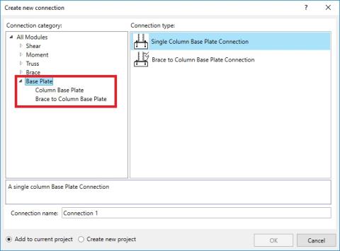
The program includes two kinds of Base Plate Connections:
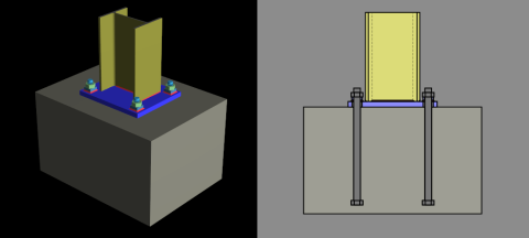
The Column Base Plate connection is a rectangular steel plate welded to the bottom of a steel column. The steel plate sits on the top of a concrete support without a grout pad between. The plate is bolted to the concrete with headed bolts that are embedded in the concrete. Options for modeling and designing these connections are described below.
In addition to designing base plates, RISAConnection now offers comprehensive solutions for full anchorage design. This new feature encompasses the detailed analysis and design of anchor rods to the supporting concrete pedestal. Note that anchorage design is available exclusively when the Steel Code is configured to LRFD.
The Brace into Column Base Plate connection is the same as the Base Plate connection above with a vertical brace gusset framing into either the column web or flange. Options for modeling and designing these connections are described below.
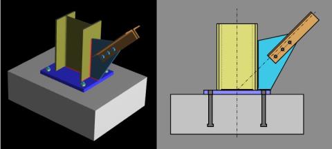
Anchorage design is not available for the Brace into Column Base Plate connection module.
If you are using RISAConnection as a stand-alone program, then you can define a Base Plate connection as follows:
If you are using RISAConnection integration with RISA-3D, then you can define a base plate connection as follows:
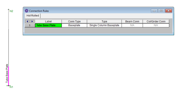
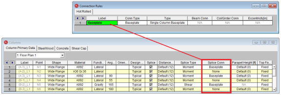
If you are using RISAConnection integration with RISAFloor, then you can define a base plate connection as follows:
Below is a list of limitations for Base Plate design:
Below is a list of limitations for the Anchorage Design:
The following inputs are available to define your Base Plate connection:
This entry is only applicable for the Brace to Column Base Plate Connection type. It controls which side of the column the brace/gusset frames into (web or flange).
This entry is only applicable for the Brace to Column Base Plate Connection type. It controls which side of the column the brace/gusset attaches to. This is important for connections with singly-symmetric anchor bolt layouts.
This setting determines the anchorage type applied in the analysis. As of the current version, the software supports exclusively cast-in-place anchors for this functionality.
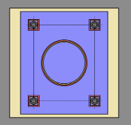
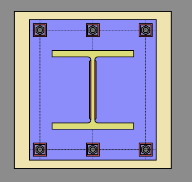
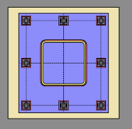
The following bolt layouts are currently available:
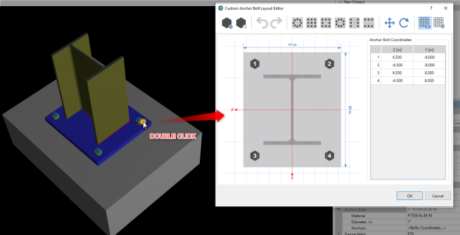
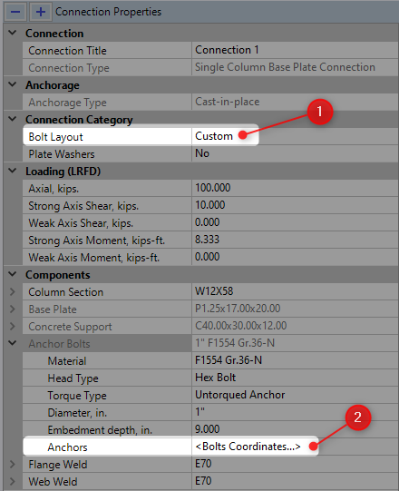
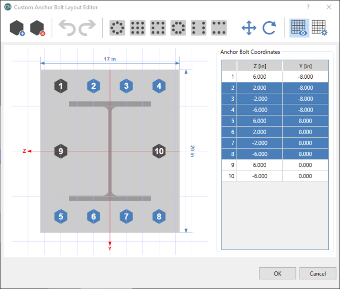
After setting the Bolt Layout to ‘Custom’ You can access the custom bolt layout by either double clicking the anchor bolts in the graphical interface or clicking the triple dots within the <Bolts Coordinates…> cell in the Anchors input. Custom anchor layouts are currently not supported for anchorage calculations.
Within the custom anchor bolt layout editor, you can perform several basic functions to customize your anchor bolt layout.
You can use the cursor to graphically click and select any of the displayed bolts. The corresponding anchor bolt coordinates will be highlighted in the Anchor Bolt Coordinates table to the right. Similarly, you can click and select a bolt from within the coordinates table on the right and the corresponding bolt will be selected in the graphical view.
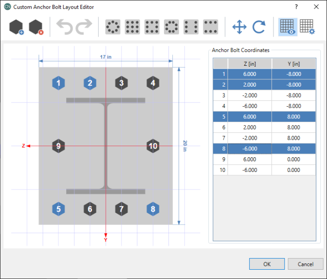
You can also select multiple bolts by holding the Ctrl key and selecting several bolts within the graphical view and/or coordinates table. If you have a bolt selected and hold the Shift key and select another bolt, all the bolts chronologically in between will also be selected. For example, in the example below, if you have bolt #2 selected, hold the shift key and select bolt #8 (graphically or in the coordinate table) all the bolts in between will be selected.
Use the  buttons to add or remove anchor bolts.
Use the  buttons to undo or redo changes made within the custom anchor bolt layout editor.
Use the  buttons to access anchor bolt templates that will allow you to quickly generate anchor bolts in various layouts.
Use the  buttons to move or rotate the anchor bolts.
Use the  buttons to toggle the display of the drawing grid and custom the increments of the drawing grid.
This option allows you to select whether or not washers are present. When present, they will have a fillet weld to the base plate around their entire perimeter.
The following loading options are available:
Axial - positive magnitude denotes compression, negative magnitude denotes tension.
Strong Axis Shear - Shear load along the weak axis of the column which causes strong axis bending.
Weak Axis Shear - Shear load along the strong axis of the column which causes weak axis bending.
Strong Axis Moment - Moment about the strong axis of the column (only applicable to "Fixed" base plates).
Weak Axis Moment - Moment about the weak axis of the column (only applicable to "Fixed" base plates).
Note:
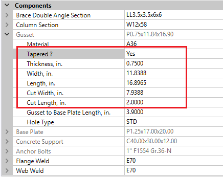
This entry is only applicable for the Brace to Column Base Plate Connection type. By default brace gusset plates are rectangular, but you may enter tapered dimensions if you prefer to have the gusset plate cut back. To select this, simply set "Tapered" to "Yes" under the Gusset plate entry. The inputs are similar to those for all vertical braces.
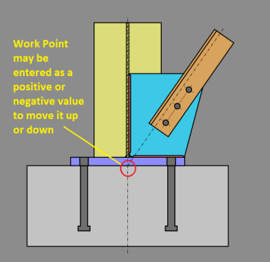
This entry is only applicable for the Brace to Column Base Plate Connection type. It controls the position of the brace to column workpoint. This may be moved up and down along the column's center-line, or left to right along the base plate. This effects the calculation of the applied loads at each sub-connection interface per the AISC Design Guide 29 methodology.
RISAConnection uses a modified version of the design methodology prescribed in AISC Design Guide 1 (2nd Edition, 2nd Printing) to design column base plates and anchor rods. The broad concept of this methodology is that yield lines are assumed where plate bending occurs, and the concrete bearing stress is assumed to be uniform at locations outside of those yield lines. The only significant modification to the AISC method is that plate side-bending is also considered (bending of the plate perpendicular to the bending moment applied to the plate). This modification is implemented per the article "Two-Way Bending of Base Plates under Uni-axial Moment Loading - Alternative Approach", published in AISC's Engineering Journal, Fourth Quarter 2014 (Volume 51, No. 4).
The base plate and anchor rods are analyzed independently for each bending direction, even if bi-axial moments are applied for the same load combination. This is because there is currently no widely accepted method other than finite element analysis for determining the bearing pressure geometry and the anchor bolt forces under bi-axial bending. Results are presented independently for both bending directions, and it is up to the user to judge what the combined interaction effects would be.
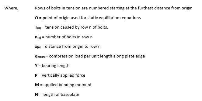
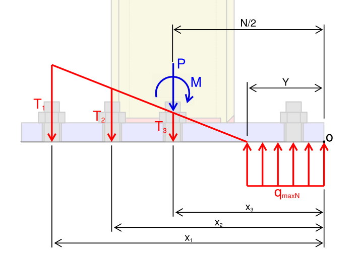
The anchor bolt forces are determined from a free body diagram currently with the Bearing Length, Y. Using the following geometry, the program solves multiple force equilibrium equations simultaneously to determine the forces in the anchor bolts experiencing tension and the concrete bearing length. The following equations/ figures are an example of this calculation being done for 3 rows of bolts in tension.
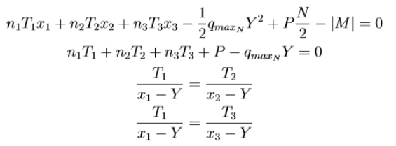
Certain configurations involving large moments and small base plates can make the algebraic equation used to determine the anchor bolt forces unsolvable. When this happens the program does not report forces, and shows the base plate as failing. Even if a solution could be found through more advanced math, the base plate would fail under these conditions anyway, so the plate must be up-sized whenever this happens.
Brace to Column Base Plate connections design the base plate using the same design assumptions as above. Additional checks of the gusset, brace, and interaction between the gusset and the column/plate are per the direction of the AISC Design Guide 26: Vertical Bracing Connections - Analysis and Design section 4.3.
The Design Guide methodology assumes:
Limitations:
Using the methods discussed above the design forces are calculated and then checked against the applicable limit states in the results report.
The following checks are included on the report:
Geometry Restrictions-
This check includes the following material geometry limits:
Load Distribution-
This "check" presents the details of the calculation to determine the bearing length of the plate in each the strong and the weak axis directions. This is done per the procedure in AISC Design Guide 1 (2nd edition, 2nd printing). For more information, see the Design Methodology topic above.
Note:
Concrete Bearing-
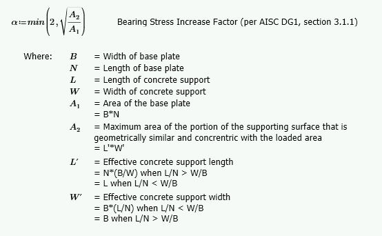
This limit state checks the bearing of the steel plate on the concrete support per ACI 318-14 section 22.8.3.2. This check includes a Bearing Stress Increase Factor, α which is calculated based on the Effective Concrete Support Length (L')and Width (W') values. L' and W' are calculated based on the following ratios:
Note:
Lateral Slip-
This limit state checks if the friction between the steel plate and the concrete is enough to resist the applied shear. It is only applicable when there is applied shear and when the axial force is in compression (i.e. a positive axial input). If this limit state "fails" then the program will assume all of the shear is resisted by the anchor bolts instead and this check will replaced by the Anchor Bolt Shear limit state.
Note:
Plate Flexural Yielding (Compression)-
This limit state checks yielding of the base plate near the compression block. It is checked independently for weak axis and strong axis bending.
For each bending moment on the column the compression block (shown in red below) causes the plate to bend about two axes.
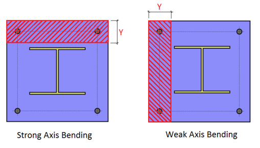
Bending about the 1-1 axis is called "Straight Bending". This bending occurs over the entire length or width of the plate.
Bending about the 2-2 axis is called "Side Bending". This bending occurs only over the length (Y) of the compression block. This bending is occurring outside of each of the 2-2 lines.
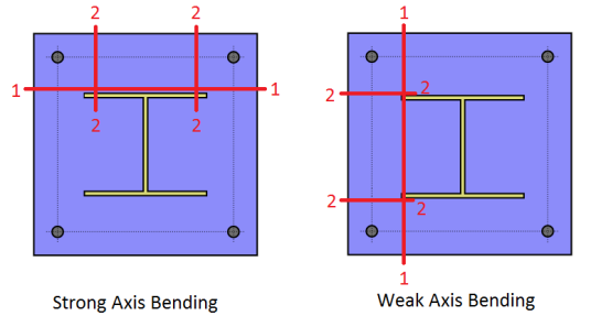
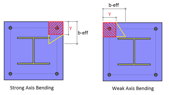
The larger of the Straight Bending Moment and the Side Bending Moment (Mpl1, Mpl2) is considered to govern, and is compared against a unit width bending capacity of the plate for this check.
Plate Flexural Yielding (Tension)-
This limit state checks the plate bending due to tension in the anchor bolts. The bending moment is calculated as the bolt tension force multiplied by the moment arm from that bolt to the nearest yield line.
The force in the bolts is determined using simple statics. The column axial tension force is equally divided among the anchor bolts then added to the force in each bolt due to overturning moment. Free body force distribution is used to determine the load in each bolt due to overturning. See Design Methodology for a discussion of this procedure and its possible limitations.
The capacity and unity check are then calculated for each bolt and the governing value is reported as the controlling value.
Anchor Bolt Tension-
This limit state checks the available tension strength of the bolts in tension per AISC 360-10 section J3.7. It is checked independently for weak axis and strong axis bending.
Anchor Bolt Shear-
This limit state checks the available shear strength of the bolts per AISC 360-10 section J3.6.
Anchor Bolt Bending-
This limit state checks the available tensile stress (calculated per AISC 360-10 section J3.7) against the total required tensile stress which includes both bending stress and the axial tensile stress from the Anchor Bolt Tension limit state (when applicable).
Note:
Anchor Bolt Bearing on Base Plate-
This limit state checks the bearing of the anchor bolt (due to the resultant of the shear loads) on the base plate per AISC 360-10 section J3.10. It is only applicable when there is shear in the anchor bolts and there are no plate washers applied.
Per the suggestions of the AISC Design Guide 1, only two anchor bolts are considered to resist the shear.
Anchor Bolt Bearing on Plate Washer-
This limit state checks the bearing of the anchor bolt (due to the resultant of the shear loads) on the plate washer per AISC 360-10 section J3.10. It is only applicable when there is shear in the anchor bolts and plate washers are applied.
Plate Washer Bending-
This limit state checks the plate washer in bending. The design code gives no direct procedure for this limit state, so RISAConnection bases it on simple physics. The bending in the plate is similar to that in a cantilever beam. The outside edge is assumed to be fully fixed where the edge is welded to the base plate. The inside edge of the hole is assumed free where the tension load is applied (at the anchor bolt).
Assuming that the washer is divided into 'n' pie slice segments, the design values are calculated as:
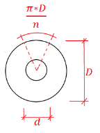
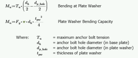
Plate Washer Punching Shear-
This limit state checks the tensile strength of the plate washer against punching shear from anchor bolts in tension. It is only applicable when at least one anchor bolt is in tension and plate washers have been applied.
Column Weld Limitations-
This checks geometric limitations of the weld at the column to the base plate. See Weld Limitations for more information.
Web Weld Limitations-
This checks geometric limitations of the weld at the column web (for Wide Flange columns only) to the base plate. See Weld Limitations for more information.
Flange Weld Limitations-
This checks geometric limitations of the weld at the column flange (for Wide Flange columns only) to the base plate. See Weld Limitations for more information.
Plate Washer Weld Limitations-
This checks geometric limitations of the weld at the plate washers to the base plate. See Weld Limitations for more information.
Column Web Weld Strength-
This checks the weld strength at the column web to the base plate. See weld strength for more information.
Column Flange Weld Strength-
This checks the weld strength at the column flange to the base plate. See weld strength for more information.
Plate Washer Weld Strength-
This checks the weld strength at the plate washer to the base plate. See weld strength for more information.
The anchorage design report includes the following checks. All references to ACI are based on ACI 318-19, unless stated otherwise. Please note that the anchorage design functionality is exclusively available when the Steel Code is set to LRFD. While RISAConnection allows for the input of moments about both the strong and weak axes independently, please be advised that according to AISC Design Guide 1 (2nd Ed.), the software does not currently integrate these inputs into a combined two-way bending analysis. Results are evaluated separately for each axis, and the results in the detail report states "Simultaneous strong and weak axis effects are not considered" for applicable limit states.
Steel Tension (Strong Axis) / (Weak Axis)-
RISAConnection performs tension checks on steel anchors according to ACI 318 Eq. 17.6.1, using the required loads from the 'Load Distribution' checks found on the Base Plate tab. Consistently, the software assumes 'Ductile' steel behavior as per ACI 318-19, Table 17.5.3(a), and applies the corresponding strength reduction factor for both tension and shear strength design checks.
Concrete Breakout (Tension) (Strong Axis) / (Weak Axis)-
RISAConnection evaluates concrete breakout in tension according to ACI 318-19 Section 17.6.2, assessing both individual anchors and anchor groups. This analysis incorporates the forces determined from 'Load Distribution' checks, calculating breakout strength based on each anchor's effective embedment depth and its proximity to the concrete edge.
Anchor group effect for Concrete Breakout in Tension (Strong Axis) / (Weak Axis)-
For groups of anchors, RISAConnection determines the combined breakout strength based on spacing and group geometry, employing the ACI 318-19 guidelines to calculate the reduced capacity due to spacing and edge effects.
Concrete Pullout (Strong Axis) / (Weak Axis)-
Determines the pullout capacity of cast-in-place anchors per ACI 318 Eq. 17.6.3.1, considering the concrete's compressive strength and anchor's bearing area.
Concrete Side-Face Blowout (Strong Axis) / (Weak Axis)-
RISAConnection conducts Concrete Side-Face Blowout checks according to ACI 318-19 Sect. 17.6.4. The check focuses on corner bolts in multi-bolt layouts due to their proximity to concrete edges. For symmetrical connections, distances ca1 and ca2 are identical for all corner bolts and clearly defined. In asymmetrical setups, the bolt with the smallest ca1 and ca2 is selected for evaluating blowout strength, using the maximum tension from any bolt as the required load. This ensures accuracy for symmetrical configurations and conservative assessments for asymmetrical ones.
Steel Shear-
RISAConnection analyzes the shear capacity of steel anchors in accordance with ACI 318 Section 17.7.1. Additionally, it adheres to AISC Design Guide 1, Section 3.5.3 for shear force distribution among anchor rods. When welded plate washers are not used, typically only two anchor rods are employed to transfer shear forces, simplifying design calculations and ensuring compliance with established guidelines. Conversely, when welded plate washers are used, shear forces are evenly distributed across all anchors, thereby enhancing the connection’s stability and strength by utilizing the full capacity of the anchoring system.
Concrete Breakout in Shear (Strong Axis) / (Weak Axis)-
RISAConnection examines the potential for concrete breakout in shear according to ACI 318 Section 17.7.2, focusing on the proximity of anchors to edges and the applied loads. It conducts Concrete Edge Breakout checks in alignment with ACI 318-19, specifically section R17.7.2.1 of the commentary. Each shear demand component, whether strong or weak axis shear, is assessed separately to precisely evaluate the concrete's structural integrity. For example, a 10 kip strong-axis shear and a 10 kip weak-axis shear are independently verified. This method ensures compliance with ACI standards, and a clarifying note at the bottom of the “Concrete Breakout in Shear” checks further references ACI 318-19 section R17.7.2.1 for detailed guidance.
Anchor group effect for Concrete Breakout in Shear (Strong Axis) / (Weak Axis)-
When assessing shear breakout, RISAConnection takes into account the layout and number of anchors in a group. This approach adjusts the shear capacity calculation considering the interaction between closely spaced anchors.
Concrete Pryout in Shear-
Checks the resistance of anchors against concrete pryout forces in shear per ACI 318 Section 17.7.3.
Anchor group effect for Concrete Pryout in Shear-
RISAConnection incorporates the effects of anchor group configurations on the pryout strength in shear. The software assesses the increased risk and potential reduction in strength due to the collective influence of multiple anchors.
Tension and Shear Interaction (Strong Axis) / (Weak Axis)-
Evaluates the interaction effects between tensile and shear forces acting on anchors per ACI 318 Section 17.8, ensuring that combined stresses remain within acceptable limits.
Concrete Splitting-
Considers the potential for concrete splitting due to tensile forces on anchors per ACI 318 Section 17.9, especially in cases with close edge distances or high load demands.
Perform Anchorage Calc-
Anchorage Design can be toggled on/off in the base plate feature of RISAConnection. This option is beneficial when engineers need to focus solely on base plate design and exclude anchorage design from the code check, preventing unity check failures due to anchorage considerations. This feature is especially useful for those who prefer performing anchorage design separately in HILTI PROFIS.

The toggle will be enabled by default, but users can disable it when anchorage design is unnecessary. When the "Perform Anchorage Calc" option is enabled, full anchorage calculations will be performed, including the display of results in the Project Explorer. When disabled, only base plate calculations will be performed, and a message will indicate that anchorage design is turned off.
In addition to the checks described above, the following checks are also included when you use the Brace to Column Base Plate connection type:
Loading at Gusset to Column-
This check is available on the Gusset/Column tab of the Results report to show the full details of the loads calculation at this sub-connection interface. This is done per the design methodology of section 4.3 of the AISC Design Guide 29: Vertical Bracing Connections - Analysis and Design.
Loading at Base Plate-
This check is available on the Base Plate tab of the Results report to show the full details of the loads calculation at this sub-connection interface. This is done per the design methodology of section 4.3 of the AISC Design Guide 29: Vertical Bracing Connections - Analysis and Design.
Column Web Bending-
This check is available on the Gusset/Column tab of the Results report. Per AISC Design Guide 29: Vertical Bracing - Analysis and Design section 4.3, the web of a Wide Flange column (or the wall of a HSS Tube column) must be designed for the out of plane bending. Equation (4-17) in the Design Guide calculates the amount of out of plane load that the web can carry per yield line analysis. RISAConnection compares this allowable value to the applied moment due to eccentricity on the column web.
Note: